Inductors Tutorial
Inductors are coils of wire.
They may be wound on
tubular FORMERS or may
be self supporting.
The former may contain a
metallic core up its
centre.
Iron cores are used for
frequencies below about
100 kHz.
Ferrite cores are used
for frequencies up to
say, 10 Mhz.
Above 100Mhz the core is
usually air and the coil
is self supporting.
At low frequencies the inductor may have hundreds of turns, above 1 Mhz only a few turns.
Most inductors have a low DC resistance since they are wound from copper wire.
Inductor values of INDUCTANCE are measured in HENRIES.

Inductors oppose the
flow of ac current.
This opposition is
called INDUCTIVE
REACTANCE.
Reactance increases with
frequency and as the
value of the inductance
increases.
Diode Tutorial
Diodes are polarised, which means that they must be inserted into the PCB the correct way round.This is because an electric current will only flow through them in one direction (like air will only flow one way through a tyre valve).
Diodes have two
connections, an anode
and a cathode.
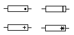
The cathode is always
identified by a dot,
ring or some other mark.

Diodes come in all
shapes and sizes.
They are often marked
with a type number.
Detailed characteristics
of a diode can be found
by looking up the type
number in a data book.
If you know how to measure resistance with a meter then test some diodes. A good one has low resistance in one direction and high in the other.

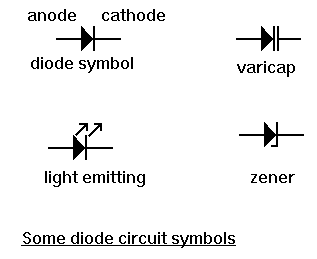
There are specialised types of diode available such as the zener and light emitting diode (LED)
Capacitors Tutorial
Capacitors are basically two parallel metal plates separated by an insulator.

Capacitor types are named after the dielectric. Thus we have ceramic, mica, polyester, paper air capacitors etc.
Capacitors can be
charged up and store
electricity, similar to
a car battery.
This can be a hazard if
they are charged up to
high voltages.
If it is necessary,
capacitors with large
charges should be
discharged via a
resistor to limit the
discharge current.
DC current cannot flow through a capacitor since the dielectric forms an open circuit.
Capacitors come in all
shapes and sizes and are
usually marked with
their value.
Values are measure in
Farads. Values in Farads
are unusual. Most
capacitor values are
measured in microfarads,
nanofarads or picofarads.
See the page on Value
multipliers to find out
more about this.

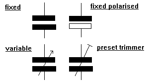
Some capacitors such as electrolytic and tantalums are polarised. This means that they must be fitted the correct way round. They are marked to indicate polarity.
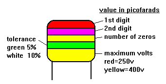
Some values are
indicated with a colour
code similar to
resistors. There can be
some confusion.
A 2200pf capacitor would
have three red bands.
These merge into one
wide red band.

For example, 102 is 1000 pF and 104 is 100,000 pF = 100 nF = 0.1 uF.
To find the total value
of capacitors in
parallel (that is
connected across each
other) their values are
added.
To find the total value
if they are in series
(that is in line with
each other) then the
following formula is
used.
1/C total =1/C1 + 1/C2 +
1/C3 etc
Variable capacitors are available in which the value can be adjusted by controlling the amount of overlap of the plates or the distance between them.

There is a type of diode
called the Varicap diode
with similar
characteristics.